In The Witness we decided that it's a good idea to have a heightfield terrain making up the bulk of the island surface. The advantages of this are in rendering performance and in ease of texturing (it is relatively easy, with one continuously-parameterized terrain block, to get rid of seams; if your terrain is a bunch of otherwise-unrelated meshes, then what do you do?) When we made this decision it seemed clear to me that the biggest disadvantage, for this game at least, was authoring the terrain. There are typically a few different ways that large heightfields are built:
- Use an external terrain editing tool and then write an importer for its file format
- Build a terrain editing tool into the game's editor (this will require a bunch of work to do a good job, and will have fewer features than an external tool but they may be more appropriate for your game; also, you can make reasonable things happen to entities placed in the world when you interactively move the terrain around)
- Paint heightmaps in an image editor like Photoshop and hotload those from the game engine (requires much less programming; doesn't provide many features, but you have very fine control over the results; unfortunately, the editing process becomes pretty cumbersome)
These seemed to be the main approaches on offer. However, I wasn't enthusiastic about doing any of the traditional things; I have written a number of terrain systems for games, and what bugged me, with respect to this game, was the way in which terrain handling tends to be very different from laying out objects in the world, and how this creates an extremely disjoint work process.
In concrete terms, this means that terrain was not going to be as malleable as the other objects in the world. I am taking a very rough-drafty approach to the game; we are building areas, then moving them across the world if we feel they will work better somewhere else, rotating them as a group, etc. The goal is to build a very-cohesive game world in which carefully-tuned gameplay is the most important thing -- where we more-or-less have a rough draft of the whole world set up before we go in and try to get serious about how everything looks.
This kind of approach just dies when you have elements that behave very differently, and are difficult to manipulate together, such as terrain and objects. If I have two hills with a path winding between them, a bench by the path with a book upon the bench, and a signpost nearby, what happens when I want to move that scene across the map and then rotate it by 30 degrees? With the entities, it is no problem, we just do that in the editor. But with the terrain it just becomes a mess to move the hills at all, regardless of which of the above approaches are used. And if you want to move and rotate the hills in sync with the entities so that the whole scene is intact... good luck!
To solve this problem, terrain needed to be built in the in-game editor, in a way that would be maximally malleable -- so that I can pick up a hill and rotate and drag it. Because of the requirement for rotation, you can't really be manipulating samples directly; it has to be control surfaces of some kind (because if you are just blitting samples around, a few rotation operations are going to mangle whatever original shapes you made).
As for control surfaces, the first ideas that come to mind are things like spline patches. But the problem with spline patches is that you have to be very careful managing the control points in a patch, and they ultimately aren't that malleable -- what if I want to split a patch in half without changing the shapes of areas near the edges? What if I want to move one small, high-detail terrain area so that it overlaps somewhat with a big, low-detail area? How is that going to work? And if I have spline patches, then any time I instantiate a new grid of patches, I have to manage a bunch of individual control points, which is labor-intensive. If I am rough-drafting, I want to do the minimum possible work to lay out a given area. If I just generally want to build a hill but don't care much about its shape, I ought to be able to do that with just 2 or 3 control points, arbitrarily-placed.
Clearly what I wanted was a system that would just look at a set of unstructured control points -- no topology or anything -- and generate a terrain from those points in the local area. When there is no topology or parameterization, you can merge and split groups of control points at will; you can have them overlap; you can do whatever you want.
I started putting together an ad hoc scheme for doing this, but did not take it very far before discovering that the mathematics for doing a good job at exactly this problem had already been invented decades ago. The method is called Kriging, and it is well known in geostatistics. If you've got a survey of height field data (or any other field data -- the density of a mineral at certain points, for instance), and that data is missing values for some locations, Kriging will give you a reasonable guess at the values of the field at the unknown points.
For rough-draft terrain modeling, we can turn the idea around; if we give a Kriging function only a small set of known data points, it will do a quite fantastic job of filling in the values at all the other points. The basic math involves the inverse of an n by n matrix, where n is the number of known data points. In theory that could become a huge computation, but for the number of points we may typically have in one local area of the map, the computation is easy for modern CPUs. Kriging is not hard to implement; I started with some public domain code written at a university and modified it for our needs (though this basically involved rewriting it, as it was messy and had some serious bugs! If anyone wants our version of the Kriging code, drop me a line).
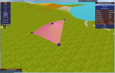
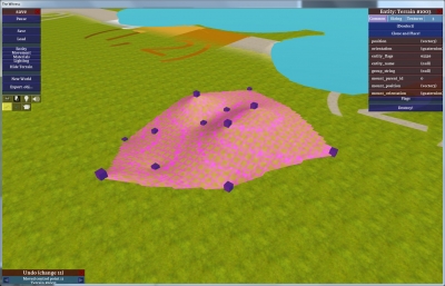
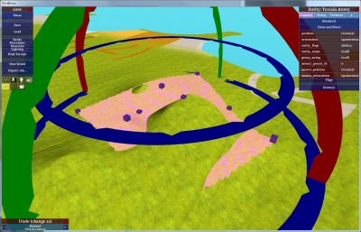
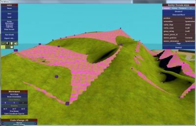
Here's how we have it integrated into our game engine. There's a type of object that exists as a set of terrain control points, which can be moved around the world arbitrarily, just like anything else. It looks like this:
The only meaningful data in this object, with respect to terrain shaping, are the positions of the control points (purple boxes). The surface is just a visualization; it tells you what surface these points would define if they were the only control points in the universe. (Though actually, the surface defined by those points would extend infinitely in all directions; this visualization stays within the convex hull of the control points, which helps you see what you are doing when editing).
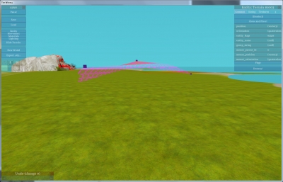
Right now these control points haven't actually been applied to the game's terrain (green surface below); they are just hovering above it. Here's a shot from another angle:
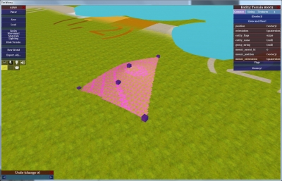
I can press a key to add a new control point to this object:
The new control point doesn't affect the shape of the old surface in any way, which is very convenient. I can drag the new control point at will:
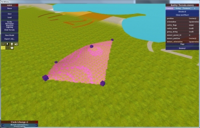
Or add many more control points:
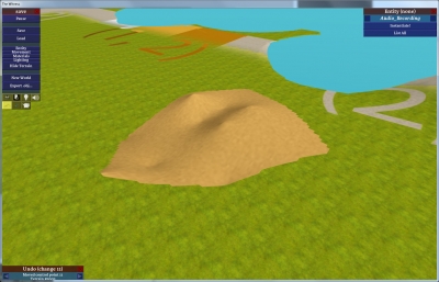
Here's that same visualization surface, with the control points and gridding turned off, so you can see it better:
Then, when I decide I like the shape, I can press another key to apply these control points to the game's terrain:
(Now there's a lot of z-fighting between the control surface and the terrain because they are in pretty much the same place.)
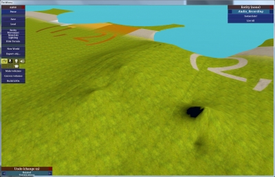
Here is the terrain with the control surface hidden. Note that the terrain values have been smoothly interpolated, even in areas outside the control object:
(By the way, those seams you see in the previous two pictures are lighting seams. These don't have anything to do with Kriging, it's just that the terrain blocks don't know how to look up their neighbors' height values when generating their surface normals. Any block-based terrain system has to solve a similar problem. It's easy to solve, but at a low priority on the to-do list, hence it hasn't been done yet. The distance between seams tells you how big the terrain blocks are, so the seams are sort of useful in this image!)
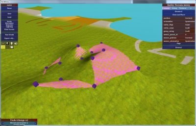
Suppose this control surface is part of a scene that I want to reorient. I'll rotate it about 70 degrees clockwise (now you'll see the surface intercutting more-heavily with the existing terrain values):
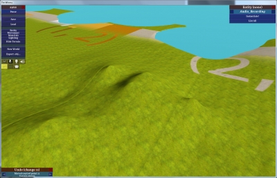
And then once again, I apply Kriging to the terrain, generating the same hills in a rotated orientation:
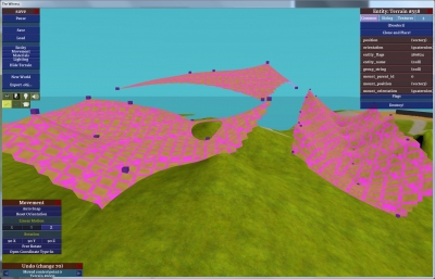
To illustrate the way that interpolation is not confined to a single control object, and that in fact this is a control point soup, here I've created three control objects:
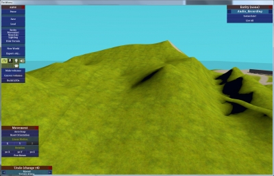
And here's what the terrain looks like with them applied:
And here's the final terrain along with the control objects (lots of z-fighting again):
Hopefully that's enough screenshots to illustrate the point. Compared to splines, Kriging has the following highly beneficial properties (aside from the huge benefits of not requiring a topology, discussed above):
- Always interpolates every control point exactly
- Adding a new control point does not change the existing surface at all.
- No funny spline-like behavior (curves appearing in strange places, huge overshoots, etc)
Hacking In Compact Support
When doing Kriging in a video game, you probably don't want to compute the terrain for the entire world at once for every change, because that would be very expensive, and it also is a little bit unintuitive (since a change to a control point very far away could change some interpolated terrain nearby, even if only slightly). However, the vanilla Kriging algorithm would require global computation and thus behave nonlocally. For The Witness we clearly wanted our control points to affect only nearby areas, i.e. have compact support. My first attempt at this was:
- Pick a radius r0 at which any control point has maximum effect, and a larger radius r1 at which the point has no effect, with smooth interpolation in-between.
- Terrain consists of contiguous blocks 33x33 samples in size.
- For each block of terrain you want to Krige, find all control points whose distance in the XY plane from any sample in the block is less than r1 (these are all the control points that could possibly affect any sample in the block).
- Pass all these points to the Kriging routine, which computes every sample in the block. It does this by building an inverse variogram matrix -- square with dimension (n+1) -- and performing one matrix-vector multiply for each terrain sample, which is pretty fast.
- For each sample, the Kriging routine gives us the set of weights we would use to blend each control point if the control points did not have compact support. To provide compact support, just compute an additional factor that is (distance - r1) / (r0 - r1) clamped to [0, 1], multiply all the weights by these factors, and then re-normalize the weights (ensure they all add to 1).
This almost works, but not quite; we get discontinuities between terrain blocks (which should not happen if everything is correct, since two vertices at the same XY position should always get the same Z value). At first I thought this was a programming error, but after looking more closely at the situation I convinced myself that the reason is mathematical. My assumption had been that a control point with a weight of 0 will have the same effect as a control point that never enters into the calculation, but this seems not to be true.
The step that I added, multiplying the compact-support factors against the weights provided by the matrix-vector multiply, is -- by the distributive property -- the same as multiplying each row of the matrix by the support factor before doing the matrix-vector multiply. If a support factor is 0, then this makes the matrix rank-deficient, i.e. it could not have been the result of an inversion, which means that this step is not compatible with the mathematical technique being applied. The idea of a 0 blend factor just isn't valid. (This also brings into question whether the idea of multiplying by the support factors is valid at all, but for now I will just observe that it produces very useful and convenient behavior. However, there are some small stepping artifacts that I see in some locations. I think these may be due to having too-low a density of control points in the world (some terrain samples having 0 control points inside r1) but there's a possibility that they aren't, and have something to do with the weighting procedure itself. I haven't investigated yet.)
Now, as I type this, I am not 100% convinced that it is the right reasoning, and that something more like a typical programming error might be the problem. My math is pretty rusty these days. However, my updated version of the routine does not have discontinuities.
Unfortunately, the fix for discontinuities has made the Kriging a bit slower. What I do is, instead of building just one inverse variogram for the entire terrain block, I build a new variogram for every vertex, and include in that variogram only the control points that have nonzero support factors. Thus the dimensions of the matrix will change from sample to sample, and I am inverting a new matrix for each output sample.
Unoptimized, this version of the algorithm takes between 5 and 25 seconds to recompute the terrain for the entire world, depending on how large r1 is. This is fine for now, especially since editing operations only hit about 1/50 of the world or less at any given time. However, it'll get slower as more control points are added to the world.
Fortunately, this first version of the discontinuity-fixing was intended to be slow -- I programmed it in the most straightforward way possible, to maximize the likelihood that it would work. It is easy to think of ways to make it faster by caching the matrices, but it's unclear which of these would be fastest. For example, if you just cache one copy of the matrix and invalidate it any time a new control point comes into or out of range, then you might easily find yourself in a situation where you oscillate between recomputing two different matrices as you work your way along the sample grid. This is a little reminiscent of the kinds of problems that 3D hardware has, which store images in a non-linear way so that they can be cache-efficient when sampled along lines in arbitrary directions... but it's not clear to me how far to take that analogy or whether any applicable wisdom can be derived from it.
So I intend to optimize it, or come up with a faster solution to the discontinuity problem, but it's not clear yet what form that will take.


Very interesting. This inspired me to try it out! =)
Is it possible to get your version of Kriging math implementation on max.dyachenko (at) gmail.com?
Thanks!
The one part of this that confuses me is the variogram. Does it learn the spatial dependence of two separated samples just based on the control points you’ve already placed? I feel like I’m missing something there.
Seems like something like compressed sensing / basis pursuit could work pretty well too. http://en.wikipedia.org/wiki/Compressed_sensing
The variogram doesn’t talk about the samples you are solving for at all. It is basically just a big matrix of correlations between the height values of the control points, where each correlation is just defined to be some function of distance that is tweaked in the way you desire. You invert that matrix; then the B vector that you multiply through is the correlations of the control points with the sample point that you want to solve for. This is a system of linear equations, the solution to which is a set of weights for each control point.
So when you are solving for one specific sample point of the terrain, you only think about that sample point and the control points; you don’t think about any other sample points. (This is a little different from the geostatistics way of thinking about it, where the control points are some of the sample points.)
Great post!
Always nice to see work from other fields put to use. Actually, I’m sure I’ll find use for this method, which is basically a structure-less control point interpolation.
I still haven’t dug into the Kriging algorithm and obviously have no idea how your terrain system works, But I do have one comment/suggestion regarding ‘compact support’ you mentioned:
Did you try interpolating surfaces instead of weights?
What I mean is, you could generate one Kriging matrix for each of the terrain blocks containing the control points from that block and extending into adjacent blocks (you can make the overlap as big as you like by increasing the radius of interest).
When trying to evaluate the height of a sample you need to sample each ‘Kriging surface’ that covers your sample and interpolate between the different surface results. Just need to figure out the weight for each surface which shouldn’t be difficult. If anything that should assure continuity.
If you have an overlap of 1/2 a terrain block (choose r = grid_block_size * 1.5) you could be done with just sampling 4 surfaces. On the down side, you might loose some local support away from the grid block centers – but with an overlap of a full terrain block you still get just 9 samples which should still be pretty fast and practically quite accurate.
Anyway thanks for all that info, cool stuff!
Interpolating surfaces suffers from the “Prussian helmet effect”. See:
Robin Sibson. A brief description of natural neighbour interpolation. In Vic Barnett, editor,
Interpreting Multivariate Data, chapter 2, pages 21–36. John Wiley & Sons, 1981.
which also gives a good interpolation scheme for scattered data (based on Voronoi diagrams), assuming you have some way of estimating the tangent plane at your data samples. And once you have the tangent planes, the interpolant is very local.
I see others have mentioned natural neighbour interpolation below. You can see a picture of the Prussian helmet effect on page 109 of http://technomagi.com/josh/math/phd.pdf .
Pretty cool and this way you could not only rotate but even do scale and uniform scale too. For example to do a narrow hill passage wider.
Natural neighbor interpolation might be worth consideration as an alternative to Kriging:
http://en.wikipedia.org/wiki/Natural_neighbor
The basic idea is to build a Voronoi diagram of the control points. Then, for each sample point on the height field grid, you pretend you’re inserting it into the Voronoi diagram. The sample point is a weighted sum of the control points from which it would have stolen area; the weight for each control point is how much area it’s contributed to the new Voronoi region.
This algorithm has local support built in so updates could be made fairly efficient. The surface is smooth everywhere except at the control points. It works well with anisotropic sample data; for instance, if you have sampled the terrain in long strips of data points, i.e. Mars orbiters:
http://pirlwww.lpl.arizona.edu/~abramovo/MOLA_interpolation/interpolation.html
I initially encountered natural neighbor interpolation years ago via Dave Watson, a professor at an Australian university. Unfortunately he seems to have dropped off of the web. I remember he had a modification to this algorithm where you could estimate (or define) normals at the control points and add those into the interpolation to get rid of slope discontinuities there.
I’m probably missing something here, but why not sum the points instead of blending between them? It might make the behavior a bit harder to control, because you’re not interpolating control points anymore, but since you can display the result exactly, does it matter? Basically each point would would be a smooth peak that you’re adding to the height of the terrain. You could still rotate a group of points. Most importantly, you could throw away the whole Kriging thing. It’s much less cool though. Another idea would be to arbitrarily group control points together, Kringe them, then sum the results. You will need to group points together by game area though, and the boundaries will be harder to control, so that may not be such a good idea.
Niv: If you decide to interpolate surfaces then you immediately lose what to me is one of the most valuable properties, which is that control points are interpolated exactly. If you want the terrain to go through a certain point, you just mark that point… that is huge in terms of modeling ability.
James: Interesting, but I worry about the idea for this kind of application. If you are inserting your samples into a Voronoi diagram, then you are always interpolating between only very-close neighbors. In cases where you are interpolating on a triangle or near-triangle (which are pretty common in Voronoi diagrams), you are going to just be linearly interpolating between 3 points, i.e. making a flat plane. So the result would exhibit hard facets very often. I think the estimation-of-normals you are talking about would be key in eliminating that problem… Certainly though, this method would be a lot faster than what I am doing, and if the smoothing makes it usable, that would be cool.
Marc: As I mentioned, I want to interpolate points. I don’t want to treat each point as an individual summed Gaussian or whatever that moves around, because that would be unmanageable, and it’s very difficult in that kind of scheme to get smooth surfaces of the shape you want without endlessly tweaking the widths and heights of neighbor points… and then if you want to make a small change, say hello to more endless tweaking. No good.
(Thinking about it more, one property that you would inevitably lose in Natural Neighbor Inerpolation is the ability to add control points without changing the surface… for example, if there is a quad in the Voronoi diagram, and you add a control point interior to it such that the new point makes a triangle with two of the quad’s corners, all the curvature inside that triangle is going to disappear. Unless again there is some smoothing going on, but then the question is, what are the properties of the smoothing and are they invariant under the insertion of control points?)
This sounds a lot like a 2d version of using radial basis functions for modeling — like James O’Brien and Greg Turk’s “Modelling with Implicit Surfaces that Interpolate”?
To speed it up, I think for RBFs with global support people have used the Fast Multipole Method to do faster solvers. Alternatively, for compact support interpolating implicits, perhaps check out the “Multi-level Partition of Unity Implicits” paper?
How many control points do you use for your whole world?
I don’t actually know how many control points are in the world right now. But it wouldn’t make sense to count yet, since it is a lot less detailed than it will be eventually, and that means there are going to be many more control points.
Will the Witness ship with the in-game editor, the way that Braid did ?
It’s unlikely. It would be very difficult to add meaningful content (due to the way the gameplay works).
On top of this, not very many people used the Braid editor. This may be largely due to the fact that it is not explicitly called out in-game, with a menu option or something. But, in order to promote an editor as a feature at that level it has to have way, way more work put into it than made sense at that time. I would expect the same thing to be true for The Witness.
My current thinking on this is, if your game is designed around user-made content, then it totally makes sense to make the editor great and expose it in a high-profile way. Otherwise, it doesn’t make sense, because the number of people who will use such an editor is not very high, and pragmatically speaking, you can add more to the world / create more interesting times for more people just by working on the next game.
An update on this…
I was working out a more-formalized way to get compact support in kriging. But even when I did it the supposedly right way, I still saw some artifacts. Researching why led me to the following complaint by Philip and Watson:
http://www.springerlink.com/content/kh71041n26070768/
(Watson is the very same David Watson mentioned in these comments by James McNeill). This referred to another paper that shows discontinuities that happen with kriging:
http://www.springerlink.com/content/r73v34635g6m1718/
Which looks exactly like the artifacts that I get when I don’t try to mitigate them, so I know that my kriging code is working properly and that we are on the same page.
This complaint and other follow-up paper were encouraging the use of Natural Neighbor Interpolation as a way of solving these problems, so I decided to try it.
With some searching I found Pavel Sakov’s nn library for Natural Neighbor Interpolation: http://code.google.com/p/nn-c/
I got this integrated into the game and working fairly quickly. The results are better than I postulated earlier in this thread (indeed, triangles are not quite faceted, I didn’t understand the algorithm so well when posting that comment). However, while not quite faceted, the shapes generated by natural neighbor interpolation are not so natural, at least for a sparse set of sample points. The results from kriging look a lot better with many fewer sample points. So now I am back to kriging and working on ways of minimizing the artifacts and speeding it up. Seeking some outside help from experienced geostaticians in this area.
I’m assuming you wouldn’t be using this technic if the PS3 couldn’t handle it, right?
None of the kriging happens at runtime, so it doesn’t matter.
In general, though, I care more about the game than about what platforms it is coming out on. So if we needed to do something for the game to reach its full potential, and that thing doesn’t work on some specific platform, then the answer is probably just not to release on that platform (or else to release an inferior version on that platform).
Do you know if Watson’s complaints about C1 continuity for Kriging apply to all compactly supported RBF interpolation methods in general? I thought some compact support RBF interpolation methods could guarantee smoothness …
Also, have you considered solving a discretized version of the problem? Often when I’ve seen people implement thin plate splines for shape modeling (which are essentially the same problem as this I think?), instead of solving for the function weights directly they turn it into a finite difference or finite element problem and solve for the vertex positions that way. It ends up giving a giant sparse matrix (one equation per free vertex), instead of a smaller dense matrix, but since sparse solvers scale much better it can turn out to be faster depending on the problem. Also, as long as the constraints don’t change too rapidly during editing, you can get a speed boost by reusing previous solutions (or previous factorizations, for sparse direct solvers).
I really have no idea about the continuity issue. About sparse vs dense, one of the first papers I read suggested going the sparse route in order to ensure continuity — in that case, you just have every control point in the matrix all the time, but most of them are diagonal elements (no effect on the result). What this means in terms of real, practical speed, I have no idea. Part of the problem is that the attractiveness of various solutions will surely change depending on how many control points there are, and as I’ve mentioned, there aren’t so many yet.
In general, though, anything that tries to re-use prior solutions, etc, etc, I don’t have patience for at the current time — it is way too easy to rathole on tech (as discussed in the comments, the shadow map memory savings thing is sort of that, though it might help on consoles). To have any prayer of shipping a game any time soon, we just have to do the simplest things possible wherever possible.
Of course sometimes it turns out that you need to do a lot of work in order to establish basic functionality. If that turns out to be true, then in this case I probably would pursue it, because this way of modeling terrain really is the right thing for this game. So, we’ll see…
I looked in to the compact support RBF methods I was wondering about, and it looks like they guarantee smoothness only within a thin area around the control points, which is useful for designing a level set function but probably not helpful when making a height field. Oops.
Hmm, actually, after implementing Wendland’s compact RBF, it does look like it’s smooth everywhere in practice (though it does fall to zero when there are no near-enough control points, of course). I made a processing applet to play around with it and posted it on the mollyrocket forums, if you want to try it out. I’ll put a link to the applet as my website, too. Note in the applet you need to press r a few times to switch it to the Wendland rbf (it defaults to the thin plate spline) and perhaps press t once to turn off the polynomial term.
Could you give some more detail re what the artifacts you see with compact support are? I’m curious to see if my applet has the same issues or not. (Unfortunately the springerlink papers seem to be behind a paywall …)
Do you use any official GUI Toolkit for your own
designed tools or did you create your own
GUI functions ?
It’s our own code based on IMGUI principles. GUI toolkits tend to all subscribe to the same retained-mode philosophy one way or the other, and require way too much work for what they actually get done.
The interesting question is, can you take a known heightfield and generate kriging control points with a minimal error for a given number of points…
Then you could pick up random areas of terrain and move them/rotate them, apply the changes back to the terrain, and be done with the control surfaces. Looking up “inverse kriging” brings at least one promising hit…
Well, here’s the thing. Because the height field is a regular grid, any rotation or non-quantized translation is going to destroy information. So this is a lossy process, which means you actually want the control surfaces to stick around so that they contain the information in a clean form; otherwise, things will degrade slowly as you keep performing these operations on them.
However, the idea still does have applicability here; if one wanted to use some other kind of tool to sculpt a local area, it would then be interesting to apply a find-the-kriging-weights system to that in order to generalize it.
Could you give me some advice on smooth embedding kriged surface into the base one?
I used both kriging and RBF in my application, but still have problems with local update of the surface.
I have tried to build some polygone around the updating region. Then I built so-called smoothin zones where I lineary smoothed base surface and new one. But this approach gives some artifacts.
You can see small pdf document with description of my method: http://ubuntuone.com/p/WVc/
Well, my system doesn’t work that way. There isn’t a “base surface” into which things are being smoothed. The terrain surface is determined entirely by kriging the various data points; the only difference at any time is which points are being considered.
@paceholder — just looking at your pdf, I can’t really tell what the artifacts are … but if the artifacts you’re seeing are related to the self-intersections in your smoothing-zone polygons, you could try using a different technique to build the smoothing zone? For example the “straight skeleton” can give you a nice offset curve that doesn’t fold back on itself.
Hi Jonathan,
I’m developing a system which will use the Kriging method for displaying data. I would be interested in the code you referred to above. I’ve not been able to find any working implementations other than a mathcad library, so if you know of any other existing code (the universities code that you reference above, for example), I would be interested in looking at that, too.
I read the whole article, but not all of the comments; hopefully what I say is not irrelevant.
The problem you reached was a result of trying to multiply by zero….what if instead of clamping the weights between [0, 1], have them asymptotically approach zero? That’s the first thing that popped into my head.
Hi Jonathan, if you’re still willing to send out a copy of the code, I’d be interested! Hoping to get away with inverse distance weighting for some interpolation I’ll have to do, but it looks like kriging would give better results, and I’d love to take a look at a working implementation to crib from.
I think I may have identified your block continuity problem, and the solution should be pretty simple.
Like you said, zeroing a row of the matrix makes it rank-deficient. However, a valid ‘variogram matrix’ (and it’s inverse) is symmetric, so if a row is zero, the corresponding column must also be zero, in which case it is still pseudo-invertible (as if lower rank).
With that in mind, consider that even if a control point’s immediate influence doesn’t reach a given terrain block, it will reach other control points in the block’s vicinity, and so the matrix will have nonzero elements somewhere along the row and column of that seemingly-cullable distant control point.
If all that is correct, the solution would be to include in the matrix for a terrain block all control points within r1 of any control point within r1 of the block (i.e. the neighborhood of the neighborhood).
(First make sure that the compact support factor is included when calculating the matrix, not just applied to the final weight vector. I assume it was, but that wasn’t clear from the article.)
A quick test, assuming you have the means to compute pseudo-inverse instead of strict inverse, would be to expand the cull radius to ‘2*r1’ instead of ‘r1’ (some null rows/columns might result).
Sorry I’m very late to the convo, but stumbled in while investigating similar things and thought that might be worth sharing.
Upon further inspection I realized that the pseudo-inverse stuff is irrelevant because the matrix diagonal will always be nonzero. It should always be invertible, even with the compact support factor cooked in the matrix (which is crucial).
The upshot is that the outlined solution should be easier to verify.