


This is a little mystery about a rock that refused to move. The rock lives off the coast of The Witness, just beyond the desert cliffs:
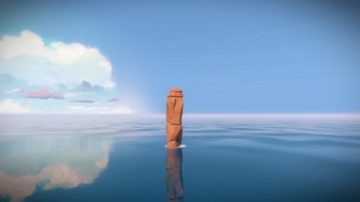
I do not know who made this rock or how long it has been there, but when I first happened upon it, I found that it resides in a nicely isolated part of the island where there’s nothing else in view, so the frame rate is always high even in full debug mode. Plus, it’s big, unobstructed, and easily pickable in the editor without fear of selecting any other objects. These properties make it perfect for testing editing features in progress, so the rock and I have become fast friends.
Normally, I do not want large rocks to move around. If I’m in the game engine, and a giant rock starts moving, I know I’m in for some debugging work. But if I’m in the editor, and I tell a rock to move, I expect it to move. That’s the whole point of having an editor. So when this cliffside rock, which otherwise had been so pleasant, decided that it would only move in certain directions, I knew I had a bit of a mystery on my hands, one that eventually forced my brain to remember some very important things it had forgotten in the ten years since I last did any serious 3D graphics programming.
Foreign Languages
Working in someone else’s codebase is much like moving to a foreign country that happens to use the same alphabet as you do, but not the same language: technically, you can read, but you don’t really have any idea what most things mean. At first, every little thing you do is a painstaking linguistic procedure, and you have to constantly check and recheck things to make sure you actually know what’s going on. Over time, as you gain more experience, you start to intuit the way things work, and you’re able to operate at closer to your full speed.
I’m used to the process of working in unfamiliar codebases since I’ve worked with so many of them over the years. I tend to approach each new one the same way: first, I write something very isolated, and keep it walled off. This lets me start making some contributions right away, while I gradually learn how to interface with the rest of the code. In the case of The Witness, this was Walk Monster. Next, I try to do some performance optimization or bug fixing, so I learn to work locally, but directly, with existing code. That was fixing the five-second stall. Finally, I start picking real features to add to other people’s code, preferably in the systems that I will most likely need to learn well.
Since I’m working on the collision system, and at this point I am certain there will need to be some interactive tools for it, I picked the Witness editor as the best place to start adding real features. After playing with it for a while, I selected two features I thought would be good additions from both the standpoint of learning the code, and for be generally useful for people working on the game. The first feature was compatible camera controls, and the second was a translation manipulator.
By “compatible camera controls”, I mean camera controls that work like common 3D art packages. My understanding was that the Witness team did their modeling in Maya, so I put a toggle in the editor that, when enabled, allowed you to use ALT-drag camera movements that replicate the way Maya moves the camera. After checking this in, I learned from the artists that some of them prefer 3D Studio MAX, so I added another button that emulates its camera controls (once you do one, it’s very little incremental cost to add others, as they’re really all just other sets of bindings for the same movements). All of this went rather smoothly.
Unfortunately the second feature, the translation manipulator, did not go so smoothly at all.
The Translation Manipulator
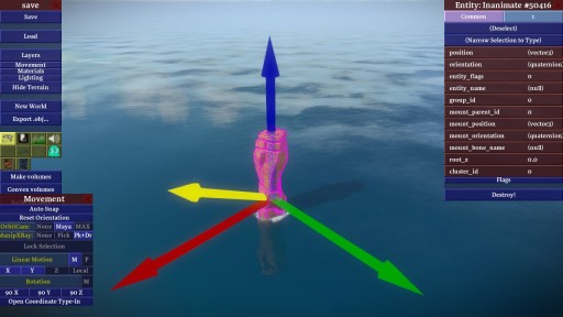
By “translation manipulator”, I mean the standard three-axis overlay that modern 3D packages have where you can click and drag on any axis and move your selection along that axis. Depending on the package, there are also little squares on each plane that allow planar movement. I chose to include these, but to allow them to be toggled separately since not all packages have them and I didn’t want them to be in the way if an artist wasn’t accustomed to using them.
Compared to the camera controls, it was moderately more work to understand all the intricacies of the editor code involved with translation. But I worked my way through it, and eventually I had a translation manipulator working reasonably well in my test world, which was a completely empty world with just a few boxy entities that I could move around to see if everything was working.
When I was confident everything was solid — undo was working, occlusion was working, etc. — I tried it out on the full Witness island for a bit. Nothing seemed immediately wrong, so I checked in the feature on a toggle switch that defaulted to “off”, and asked Jon to check it out when he got a chance. I figured it was better not to check it in enabled by default and have the artists all start using it, only to find out it had some critical bug that would corrupt things in some irreparable way, losing lots of valuable work in the process. Since Jon does a lot of work in the editor, and he wrote a lot of the editor code originally, I figured he would know the things to try that might break so we could fix them before any real damage was done.
When I heard back from Jon, he said it did seem to be working correctly, but sometimes “moving along the Z axis wasn’t working”.
The Occasionally Movable Rock
I was not at all surprised to hear that Z-axis translation was unreliable. This was something I was expecting to have happen. Surely something was broken in the way my code interacted with the existing planar movement constraints, which were buttons the editor had always provided and which were the only way of constraining interactive movement before I added the translation manipulator. But I checked the code thoroughly, and I just didn’t see any way that I could be mishandling the Z axis in the intermittent way Jon had reported.
I tried playing around with movement more in the editor, to see if I could reproduce the problem myself. Soon, I started to notice that when I played with the solitary rock in the ocean, it wasn’t really “sticking” to the cursor as well as it should be; the code I had written was supposed to feel as if you had “grabbed” the manipulator, and it should follow your cursor rather exactly. It wasn’t doing that.
Then I noticed something even stranger. Depending on how I rotated the camera, I was able to find angles at which Y-axis dragging moved the rock extremely slowly even for large cursor movements. At one particular camera angle, the rock refused to move along the Y axis at all! For example, at this angle, I could move the rock along the Y (green) axis, albeit slowly:
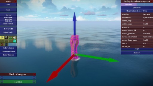
and at this angle, I could not move the rock along the Y axis at all:
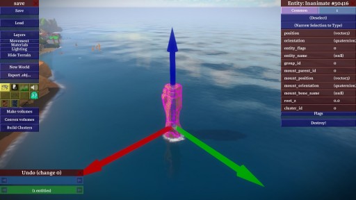
even though the other two axes worked fine, and from other camera angles the Y axis worked fine, too. Since the manipulator supported entity-relative axial movement as well as world-relative axial movement, I tried switching to entity-relative axes to test if there was something wrong with the Y axis specifically. I rotated the rock such that the Z (blue) axis was pointing in the direction that the Y axis pointed previously:
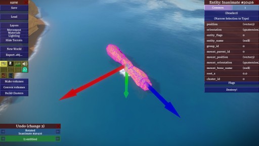
To my surprise, it now refused to move along Z! So it really had nothing to do with which semantic axis you were moving, it seemed to be the direction in the world and the angle of the camera alone that mattered for reproducing the bug.
Looking for more ideas about what the bug could be, I tried loading the empty test world again and playing around with the manipulator there. Again, to my surprise, it was completely impossible to reproduce the bug. No matter what camera angle I used, or where the axes were pointing, the always dragged perfectly, and seemingly at the correct speed to boot.
What on earth was going on? Clearly, it was time to think more deeply about the code and the behavior it was exhibiting.
Ray Versus Plane
In most 3D editing operations, you must confront the problem of turning a 2D cursor position into something useful in three dimensions. Since a 2D point on the screen mathematically represents a ray in three dimensions (everything in the world that is “under” that point from the perspective of the user), this typically involves taking the ray and intersecting it with something. For example, to implement picking of objects in 3D, you typically intersect this 3D ray with the objects in the world, and you see which intersection is closest. That will be the closest object under the cursor when the user looks at the screen, and therefore the one that they most often expect to pick when they press the mouse button.
My translation manipulator also works by intersecting the ray implied by the cursor. Knowing which axis the user clicks on is analogous to the picking problem, and I essentially implemented it that way: I pretend that there are three long, skinny boxes that align with the axis arrows, and I test to see if the cursor ray intersects them.
Picking the axis is straightforward, but things get more complicated once dragging begins. Although I know which axis the user started dragging, in order to actually move things properly, I have to have a way of computing exactly how far they have dragged the object along the selected axis. Intuitively you might think well, why not just extend the box used to pick the axis to be infinitely long along the dragging axis, and continue intersecting with it as the user moves the cursor? That’s not a bad idea, and it would work, but it isn’t the best solution.
The reason is because it doesn’t feel very good to use. Although it will feel fine if the user drags right along the axis in question, a lot of times users don’t do that. They tend to drag erratically, and pay more attention to the object’s position than how closely they follow the line implied by the axis. This quickly moves the cursor off the imaginary box entirely, so the ray implied by the cursor won’t intersect it. This causes the manipulator to stop working until the user moves the cursor back onto the axis, resulting in a sticky and unpleasant user interaction.
What we’d rather have happen in this case is for the dragging to happen as if the user had moved the mouse to the point on the axis closest to where they actually dragged, even when they’ve wandered quite far from the axis itself. To see how to solve this problem geometrically, imagine a user dragging the mouse along the X axis of a 2D plane. If the user starts dragging erratically, and moves along Y as well, their cursor will end up out in the middle of the plane somewhere. Figuring out where they would have been on the X axis is quite simple, though: ignore the Y coordinate, and just use the X coordinate. Nothing could be simpler.
But how do we do this operation for an arbitrary 3D axis and a ray extending from the cursor? It turns out you can do it exactly the same way. All you have to do is pick a 3D plane that happens to contain the dragging axis, then intersect the cursor ray with that plane. That gives you a nice 2D coordinate on a 2D plane, where the dragging axis is analogous to the X axis in the simple example. You then “throw out the Y”, and are left with a drag that always feels nice in 3D, sticks the object tightly to the cursor, and does not require the user to drag close to the axis.
You don’t need any fancy math to do this. It’s entirely constructible with simple operations available in any math library: dot product, cross product, and ray-intersects-plane, all three of which were already available in The Witness codebase.
So my translation manipulator was built entirely out of the most basic 3D operations in any math library. Yet somehow it was exhibiting very odd behavior atypical for a simple system. How could this be? What was I missing?
Debug Rendering
My first thought was that I must be picking the dragging plane poorly. Constructing planes in 3D with only partial information is always a little dicey; you need three non-collinear points to define a plane, but often you want to construct one with only one or two points. The translation manipulator is a perfect example: it needs a plane to operate, but it only really has a line to work with, which is equivalent to only two points. There are, in fact, an infinite number of planes that pass through the dragging axis of the translation manipulator. It’s much like a waterwheel: the dragging axis is the center axle, and each blade of the wheel is another valid choice for a plane.
So how do you pick one? The best method I’ve found for translation manipulators is to use the location of the user. Since we want the user to be able to drag around on this plane easily, it makes sense to say that, of all the planes containing the dragging axis, the best one is the one that is most visible to them. This avoids the potentially bad cases you can hit if you pick something independent of the user’s location, such as the resulting plane being edge-on or nearly edge-on so that the user cannot actually drag along it effectively.
Since even simple 3D math like this can be difficult to verify by inspection alone, my first inclination was to add some debugging rendering to verify that I was picking the dragging plane properly. Since the camera angle clearly mattered, and the plane was one of the only things dependent on that angle, it seemed like a likely culprit. So I tried drawing the normal to the plane in yellow at the base of the manipulator:
Even in the cases where the dragging failed, the plane normal looked right. Maybe the positioning of the plane was wrong? I tried computing the location of the plane directly, by moving along the normal by the plane constant d and drawing the normal there. This, of course, put the normal nowhere near the manipulator, so I had to look around for it (the plane equation gives you the point closest to the origin, which has no real relationship to where the manipulator might be, other than that they both lie on the same infinite plane). But once I found it, even though it was far away, looking back toward the manipulator it still did seem like it was the right plane.
Next I moved onto the intersections. I tried drawing the intersection point that I had computed when picking the axis in the first place, and also the point that I used to compute the plane constant in the first place. Both looked correct.
But then I tried drawing the actual intersection computed at each drag update, and that didn’t look correct. In fact, it didn’t really “look” at all. Although I was specifically telling the renderer to draw a white sphere where I’d found the intersection of the cursor line with the plane, no white sphere appeared. I checked the code again, and it looked correct, so I tried doing a few more test drags, this time from angles that had seemed to be working before. Now, the sphere showed up, although it was bigger than I thought it should be, which was odd.
I tried rotating the camera. I wrote the code so as to leave the sphere rendering wherever the last dragging intersection occurred, so if I stopped dragging, it just stayed where it was. This allowed me to rotate the camera and see precisely where the sphere was located, and as I did, I realized that the reason the sphere appeared too large was because it wasn’t even close to being on the plane I thought I was using. It was much closer to the camera. Weirder still was that, at the buggier camera angles, the sphere was jumping around erratically, and wasn’t really sticking to the cursor, which it always should do no matter what plane was being used. I was, after all, intersecting the cursor line with a plane. How could the intersection point possibly lie anywhere but directly under the cursor, regardless of the parameters of the plane?
It was at that moment that my math brain finally woke up. It had been sleeping for about a decade, which is how long it’d been since I’d done any real mathematical programming. In an instant, I immediately knew both what the problem was and how to fix it.
Always Look Behind You
The problem was embarrassingly obvious when you consider the clues I’d been generously given and yet completely ignored. Remember when I said I drew the plane normal at the location indicated by the plane constant, and I had to look “far away” at the manipulator to see if it looked like it was in line with the plane? Well if the generally erratic behavior of the manipulator hadn’t been telling enough, that little episode should have been the dead giveaway.
At this point, every serious 3D programmer who hasn’t been doing other work for ten years surely knows what the bug was. But for the sake of people who are less experienced, I decided to end this article with a bit of a cliffhanger.
I am going to tell you that you can find the bug by looking at this simplified version of the ray_vs_plane function in The Witness that I was calling (the real version does some epsilon checking in case the ray and plane are parallel, but otherwise it is identical):
Vector3 ray_vs_plane(Vector3 ray_origin, Vector3 ray_direction,
                     Vector3 plane_normal, float plane_d)
{
    float denominator = dot_product(plane_normal, ray_direction);
    float numerator = dot_product(plane_normal, ray_origin);
    float t = -((plane_d + numerator) / denominator);
    return ray_origin + t*ray_direction;
}
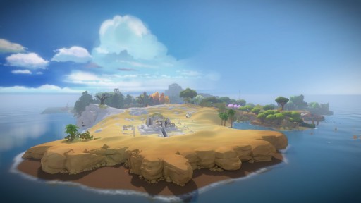
And I will also show you this screenshot of what it looks like if you turn around 180 degrees from the rock and look back at the island itself:
But, until next time, I’m not going to tell you what the bug actually is. Can you find it, and figure out how to fix it, before then?
You say the sphere was much closer to the camera than it should have been, so my guess is that you were picking the wrong points to define your plane and the plane you were using was sometimes passing too close to the camera, or else behind it, because it wasn’t actually positioned on the manipulator center like you thought it was by checking the plane offset from afar.
That ray vs plane intersection code still returns an intersection point in the negative direction when the ray is pointing away from the plane, so if the plane went behind the camera, it would result in a point being picked behind the camera. This could explain some of the disappearing spheres you mentioned, although depending on how the non-intersections are handled it seems like that should cause translation to be backwards which you didn’t mention. If the plane were just coming very close to the camera, it would explain why translation would be very slow. The section of the plane visible from the camera would be very small, causing the intersection point to not move far with the camera movement. If the plane perfectly intersected the camera position, it would be impossible to translate at all.
The screenshot showing the plane normal might not be right. If the plane is always oriented to face toward the camera as much as possible, shouldn’t the yellow plane normal and the Y axis appear co-linear from the camera’s perspective?
*The section of the plane visible from the camera would be very small, causing the intersection point to not move far with the _mouse_ movement.
Should I do “hot and cold”, or should I just let everyone answer without commenting? ;)
– Casey
Hah. We’ll see if anyone gets it…
On the one hand, it is fairly subtle, but on the other hand, no it isn’t, understanding this issue is absolutely required to be a good game programmer. So, uhhh… we’ll see who gets it!
Roger that – I will only answer clarification questions, then :)
– Casey
Is the plane only instantiated once, or does it update as you move the camera to continually face it?
Can I know what exactly is the variable ‘t’ calculating….Is the semicolon for “return” missing?? I don’t think that in the return ray_origin (the return is giving the new position for the object isn’t it??) needs to be added to t*ray_direction coz already in the ‘t’ the numerator’s value (plane_d + numerator) is calculating that new position…
Thanks for the semicolon catch, Aditya – it was a typo, there should have been a semicolon there. I have updated the article to include it.
As for your question: this routine uses the standard “solve for t” method of finding the intersection point between the ray and the plane. You can actually search for “ray plane intersection” or other such things on Google, and you will get a lot of hits describing this exact math for this exact problem if you would like to read a complete description (or two :)
As to what the function returns, because both the plane normal and the ray direction are unit vectors, the resulting t is the distance along the ray you would have to go from the ray origin to get to the intersection point. Thus the return value from the function, ray_origin + t*ray_direction, is the intersection point of the ray and the plane.
– Casey
Thanx…Ill search it and give back a reply if I get it :)
Do we have to reverse the normals for some instances depending on if t comes out to be greater than 0 and the values of x,,y, or z have a reverse sign to the normal??
Something like the example given here (http://www.siggraph.org/education/materials/HyperGraph/raytrace/rayplane_intersection.htm)
I’m far from being a serious (or even novice, really) 3D programmer, but I’ll take a stab in the dark at it: the bug occurs when the viewing direction is perpindicular to the plane normal, causing the dot product to return zero. So ray_vs_plane() is just returning the ray origin, which would explain why the intersection point is too close to the camera.
Regarding Ted’s question above (WordPress is not letting me reply directly for some reason): the plane updates continuously, so when the user rotates the camera, the plane is recalculated. And I will reiterate that you can find the bug solely with what I posted in the article – you do not need to consider things for which I did not post the code, like how I was calculating the plane, or how I generated the cursor ray, and so on. Assume those are all correct.
– Casey
I think there is a max reply depth. At some point we ought to update this theme…
It’s lovely and fitting to your sort of aesthetic, but unfortunately the comments section is often a mess.
It’s because of lack of precision in ieee754. The translation manipulator needs three points: two on the axis and the camera. However, on your rock that is far, far away from the main land the coordinates of the three points are very large. But the distance between the object you’re manipulating and the camera is relatively small. When you plug these values into a dot product, you will basically be multiplying two large numbers together, giving you a very large number. In the very large number, it will just truncate the least significant bits of the product. The least significant bits hold important information about the distance between the camera and object, since the most significant bits are busy telling you how far you are from the origin. The floating point numbers can’t keep track of the large distance from the mainland, yet also the small distance of the camera and object. ieee754 can’t hold these values since the fraction of a floating point number (single precision) is just 23 bits. It’s not infinite precision. It will just round away the important information that you want: the location of the cursor. This is why you didn’t have problems in the test world, all of the coordinates are close to the center of the universe and thus small. And your hint of looking behind you makes sense, since it shows you’re far from the island and thus the coordinates are large.
The large distance would make t essentially zero out, it’s true, but I got stuck on some problems when I thought about this. First, it seems like since we’re always close by the rock, the dot product involving ray_origin would not change by much, hence this answer would not depend on the camera angle. Second, it does not explain why the intersection point would leave the cursor at any point, as mentioned. That’s what is really grinding at me, it doesn’t seem possible given what’s being returned by the function.
The solution would be to just translate all of your coordinates so that the origin is near the object you are manipulating.
After more reflection I came to the same conclusion as Tyler as to the nature of the problem, although this answer is incomplete: Why does the problem only occur at certain camera angles?
This is because of the nature of the dot product. The dot product goes to zero as two vectors approach 90°. When the camera is facing away from the origin, the ray direction is in the same direction as the ray origin vector, so the dot product is very large. When the camera is turned 90°, it approaches zero, so there is more precision available. At the same time, as the camera rotates 90°, the plane rotates about the axis so it passes closer to the origin, which means the plane_d is also smaller and more precise. This is important because if you add a very small number to a very large number (for instance a small numerator plus a large plane_d), you may just lose all the information in the smaller number to rounding error.
What this means in terms of the ray-plane intersection code is that when the camera is facing toward or away from the origin, the plane_d and numerator are both very large, so the least significant bits may be lost in the dot product. However, when the camera is turned 90°, the plane_d and numerator will be both much closer to zero.
How to fix it? Translating to the origin would certainly solve it, or just using double just in the computation instead of float could be an alternate simpler solution than translating the problem to the origin that also improves precision in other parts of the game. That would have the side effect of making physics computation a bit more expensive, depending on how much this particular function is used in the physics engine and whether the game is running in x64, so I’m betting you didn’t use double to solve the problem.
The data returned is always a point on the line passing through the cursor, in the direction of ray_direction. If ray_direction were perpendicular the plane of the user’s camera, the white sphere would always have to be underneath the cursor. Hence we can conclude that since the sphere wasn’t sticking to the cursor, the vector ray_direction has to be something other than described (Alternatively, we can conclude that I’m mistaken and I’ve misunderstood something).
This provides a possible explanation for Tim’s observation that the normal vector is not quite what it should be to align with the user’s camera, as that calculation would be made using the normal vector to the camera. He believes it should be co-linear with the green vector; I actually think it should appear horizontal with respect to the camera.
If we did something to ray_direction like, say, forget the z-coordinate, we would increase the angle slightly, hence the denominator would increase slightly (this statement is highly dependent on the particular angles involved) which would artificially shrink the distance t, placing the claimed intersection point closer to the camera. This might provide an explanation for why the intersection points were closer than you expected in some cases.
From your “look behind you” hints, I am guessing that the nonworking camera angle is exactly that where the camera lies on the line between the rock and the origin. I’m not yet sure how this might factor in.
A problem with what I’ve written is that I find it very implausible that such a simple mistake would be made with ray_direction. Yet something is wrong if it ever leaves the cursor, either with ray_origin or ray_direction.
So the last guess I would have is that maybe the ray_direction is calculated correctly, but the perspective makes it seem like it’s not pointing in the proper direction. That would at least explain how the intersection point could fail to align with the cursor.
The “erratic jumping around” part immediately suggested floating point precision error to me – ie the denominator came close to zero. Depending on how your div by zero is set up, I would think occasionally your result is propagating NaNs and sometimes just wildly inaccurate when the ray vector points in certain directions…
Divide by zero will only happen when the ray and plane are parallel because the dot product only returns zero for perpendicular vectors.
You should test for t > 0 to get an actual ‘ray’ vs plane test instead of a line (extending in both ways)
Could it be that the rock is far away from the coordinate system’s center so both plane_d and ray_origin are huge resulting in overflow in the dot products?
This would cause the division to be a huge float over a huge float, resulting in erratic floating point operations.
My first instinct was to check whether the ray direction and plane normal were normalized vectors, but the math works even for non-normalized vectors.
I think the reason for the plane normal not being colinear with the Y axis is just because it uses the camera normal in the calculation rather than the direction from the camera to the point.
I think you can ignore problems with the way the ray and plane are calculated. as Casey wrote above: “you do not need to consider things for which I did not post the code, like how I was calculating the plane, or how I generated the cursor ray, and so on. Assume those are all correct.”
(Sorry, this was supposed to be a reply to Ted’s comment above but WordPress got weird when I messed up the captcha.)
The ray is intersecting with something behind it (the geometry of the island behind the rock).
may it be a confusion interpreting the parameters of the plane equation? if when you drew the yellow axis displaced at plane_d * plane_normal, and the manipulator and axis where indeed in the plane, that means the plane equation is dot_product(plane_normal, point) == plane_d, but when you solve for t you are solving dot_product(plane_normal, point) + plane_d == 0. if that’s the case, the third line should read float t = ((plane_d – numerator) / denominator);
Although that’s certainly a mistake I’ve seen people make, it was not the problem in this case. As I said earlier in the comments, you _do not_ need to consider code outside the snippet I posted to find the bug.
– Casey
I’m not sure if this was already made clear, but is this rock going to appear in the final game? I couldn’t quite understand if this was a rock placed for testing purposes or if it’s supposed to be part of the final geography of the island.
I think I would enjoy coming across this rock and remembering this post.
Sebastian: I’m afraid I don’t actually know if the rock will be part of the final game or not. It was not put there for testing purposes, but the island is constantly being reworked and upgraded by Jon and the artists, so the rock may be replaced, refined, or removed as part of that process before the game ships.
– Casey
It’ll be in the final game.
GOOD. Now I’ll buy it for sure.
So here’s my zero-knowledge proof of knowledge! :)
1. To reproduce this bug, you do not need to start a long time ago, but it sure does help if you live in a galaxy far, far away.
2. There’s a very simple fix that gets rid of all the symptoms but not the underlying issue.
3. If it was a meteor rather than a rock floating in the sea, you would’ve noticed this much earlier.
4. In an ideal world, we wouldn’t have this problem.
5. One way to fix this notes that it’s a good thing that lines are linear; and sometimes a little redundancy goes a long way.
6. Another way is based on the realization that while it may be more work, sometimes moving the mountain to the prophet is in fact the right approach.
Love it :)
– Casey
I’m not an expert but I’ll give it a try.
My though is that numerator is too high and I would fix it by normalizing ray_origin in the dot product.
float numerator = dot_product(plane_normal, normalize( ray_origin) );
Hope it’s not too stupid.
It once took me two hours to find the bug in this code:
sines.x = sinf(o->angles.x);sines.y = sinf(o->angles.y);
sines.z = sinf(o->angles.z);
cosines.x = sinf(o->angles.x);
cosines.y = sinf(o->angles.y);
cosines.z = sinf(o->angles.z);
I don’t think this challenge is for me. Eagerly awaiting the follow-up post and answer.
Eugh! Euler angles!
I don’t understand quaternions and for what I’m doing I don’t care about gimbal lock.
You said the origin of the ray is the camera of the user. But isn’t the origin of the coordinate frame usually the camera in 3D games?
Then “ray_origin” in “float numerator = dot_product(plane_normal, ray_origin);” would be the nullvector.
I don’t know anything about coding, but looking at the picture of the island – has the bug cause the whole island (and the sea) to flatten into a plateau? I feel like the shoreline in the foreground of the image shouldn’t look like that, I can see that some of the trees are submerged, and there’s something weird going with the ship in the background.
There are a lot of things about the island that are still in progress / placeholder / etc., but this bug doesn’t have anything to do with any rendering glitches or unfinished geometry you might see in the screenshots. The bug only affects the translation manipulator.
– Casey
This by the way, is why I can’t be bothered to learn. That page elevates the obtuseness of the Wikipedia math article to self-parody status.
First sentence:
What? This is like saying in the first sentence of an article about tangerines that “Tangerine is a word.” It continues:
Thanks for the history lesson, but it still hasen’t explained anything.
Hmm… okay. “A feature of the word tangerine is that it has 9 letters.”
Quaternions find uses in both theoretical and applied mathematics, in particular for calculations involving three-dimensional rotations such as in three-dimensional computer graphics and computer vision. They can be used alongside other methods, such as Euler angles and rotation matrices, or as an alternative to them depending on the application.
Finally! Now it’s going to go into detail, right?
The unit quaternions can therefore be thought of as a choice of a group structure on the 3-sphere that gives the group Spin(3), which is isomorphic to SU(2) and also to the universal cover of SO(3).
Are you kidding me? If you think in terms of concepts like these why are you reading a basic math article? The only thing in that whole wall of text that’s of any use to a layperson is the notation.
Well, Wikipedia is not necessarily supposed to be a good place to learn math. It’s a reference.
If you are going to let an explanation you don’t like sour you on an entire concept, well, that does not seem very productive toward being one of the Smart People In Game Programming. There are lots of bad explanations out there; the key is just finding the ones that are maximally useful to you at the current time.
For an extremely stripped-down summary (it won’t tell you all that much, but it is easy to understand), see Paul Bourke’s code documentation: http://dkerr.com/Quaternions.htm
For something that will give you more intuition, but is still not bad to follow, see David Eberly’s “Quaternion Algebra and Calculus”: https://dl.dropbox.com/u/2970717/quaternions.pdf
From there, you can try a book like “Visualizing Quaternions” by Hanson… and then maybe “Hypercomplex Numbers” by Kantor and Solodovnikov, if you want to see more about how they fit into the system that goes Real -> Complex -> Quaternion -> Octonion.
And let me just follow this up by saying: Quaternions are a very serious thing. Without understanding them, one probably can’t become a good 3D programmer. I recommend learning how they work, as they solve a lot of really basic problems.
How about rotors?
If you are talking about 3D space only, then rotors are actually the same things as Quaternions. They just let you generalize to rotating 2D things directly without having to do the shenanigans you normally have to do. (Except actually, they do the same shenanigans, it’s just they do them in way that is abstracted into the basic way they work).
I am a fan of Geometric Algebra in general, and I use that kind of reasoning pretty often when I do math on paper. One doesn’t tend to do it in code though.
Can we expect a The Witness Tactics when this come out?
“The Witness: Tactics” will be available exclusively as DLC to anyone who pre-orders “The Witness: Collectors’ Edition” through select retailers before April 1st. This will also be the only way to get the Witness-themed swimsuit DLC for “Braid or Alive: Beach Volleyball”.
– Casey
That actually made me laugh out loud :D
I’d pay for Timothy in a swimsuit.
Is it picking back-facing planes from the geometry behind you? :)
(Actually, you might be inside a geometry picking back facing planes… long shot)
Pardon my ignorance, I’ve always used a library for this type of stuff, but why do you convert the mouse into world space instead of projecting your object axes into screen space and calculate your offset with 2D math?
I’m not sure if you’re asking the general question, or just specifically for dragging the transform manipulator. If you’re just asking about dragging:
The dragging behavior has to feel right, as if you have “grabbed” a point on the object or manipulator and are “pulling” it across the screen. In order to do this, you need a way to relate a position on the screen with a position in world space. If you only project forward to world space, you won’t have any idea what to set the actual coordinates of the object to in order to make it appear as if it is attached to the cursor as the user drags it around. Ie., you can project the object’s location into screen space, and then you can know how far in screen space they have moved it, but then _how do you know how far in world space they have moved it_? You have to back-project into world space at some point, so you will still be faced with the 3D math problem at that point.
If you were asking why we use this in general:
1) It is much less expensive to project a single mouse ray back into world space than it is to project all the objects into world space onto the screen to test them for picking.
2) Projecting things onto the screen is always a little dicey, because things explode when you get close to the viewpoint, so you would have to make sure you actually did things properly with the projection and clipping and so on, which is actually somewhat involved to do right. Back-projecting the mouse ray, on the other hand, is pretty trivial and only takes a few lines of code.
3) In order to pick things in the properly sorted order (ie., things closest to the camera get picked first), you still have to remember things like the depth of each triangle that you’re testing, and you have to interpolate that depth in a perspectively-correct way, too, to get the depth at the intersection point, etc., etc. Either that or you’d have to use feedback or render a hit-testing buffer through the GPU with ids that let you identify the objects in question, all of which ends up being a lot more code with a lot more hardware dependence than the simple back-project-the-mouse method.
4) A variety of other reasons I’m not thinking of at the moment.
– Casey
Actually I was just thinking about the part after you’ve selected your object and direction. Wouldn’t the translation be: position’=ray_origin + t*ray_direction where t is calculated in screen space as
t = dot(ss_mouse_current- ss_mouse_down, ss_ray_direction) /length(ss_ray_direction)
(In case I have a math error… the formula is supposed to be the screen space distance of mouse travel along the screen space projected translation vector)
Actually as I type this I realized the issue. While it would work at a basic level, the object wouldn’t track the mouse perfectly unless the direction vector was just the right length. Calculating that length would be as much math as just doing it your way. (if not more because of perspective correction)
Thanks for the detailed response!
It’s pretty clear to see that the people who are right here are quite right. As a person who has written several implementations of procedural generation of planet-sized objects, I feel silly for not realizing the true problem sooner.
That must have been an awfully fun puzzle to solve. Thanks for sharing!
Well, there’s nothing wrong with the pseudocode :)
Except that if you want a semiinfinite ray, you should make sure that t is > 0.
Haven’t thought much about the bug, but I love the clouds in the screenshot.
Is it that the plane is being created at the (0,0,0) of the world instead of the opbject being manipulated, or vice versa?
I also thought maybe it was being re-created over and over again as you move the cursor in a position relative to the camera or cursor, or relative to the object which has since moved from its original position.
Long time reader, first time poster. I don’t want to take up a lot of your time because I’ll freely admit the math is beyond me practically (if not conceptually…); the writing, however, is excellent! Thank you, Casey, for taking the time to present such an interesting snippet in such detail and in a way that is engaging and accessible to even to a layperson. Well done, and I eagerly look forward to reading more of your posts!
I know it’s been posted a few times, and since I have rather little 3d programming experience I assumed that I was jumping to a dumb conclusion. But I feel like it reeks of precision errors with floating point numbers. If the plane constant is a small floating point value, and the vectors which are describing the picked object position and the translation motion are significantly far away from the origin of the world. Then the small plane constant can easily get lost in that division of the massive world coordinate floating points when the hardware simply truncates the division and rounds it off.
I may be wrong, but it seems to explain why the problem did not show up in your test world, because the objects you were manipulating we’re close to the origin, and therefore not susceptible to the rounding errors when the points were projected onto the world plane. It also explains why it was a problem at some camera angles and not others, because the projected point would be closer or further from the plane origin, and therefore larger or smaller. Also, you may notice odd precision increases or decreases based on proximity to whole number results.
I’m mostly talking out my ass here, as I’m not the best programmer in the world. But I enjoy a good puzzle. So I couldn’t resist embarrassing myself.
As for how to fix the issue. I suppose you could simply define the projection plane with an origin that is closer to the object in question. Or Iover hiking backwards and you could just make the objects translation be in local space instead of world space and then reproject the translation after the math is completed in a smaller domain.
Ugh, iPad autocorrect made me sound dumber there.
Obviously were instead of we’re.
And I’m thinking backwards instead of Iover hiking backwards.
plane_d -?
hi!
i have an important question…
when will you release this game??!!!
im waiting for about a year and checking your blog every week,
you know…im a crazy fan of puzzle games!!ive played the fantastic game “braid” and i love it…it is,seriously without exaggerating!,the best puzzle game ive ever played.and now i want to try “the witness”.so i would be happy if you just say a date of releasing it!!
thank you.
The Witness is an ambitious game, developed by a small team with a limited budget, so the truth is simply that it isn’t really possible to accurately predict when it will be done. Everyone is working very hard to make it perfect and put it out there so people can experience it, but there’s always a ton of work to do to finish a game, especially if you want it to meet a high quality bar.
So thanks for being patient, and I hope you find that The Witness was worth the wait when it comes out!
– Casey
Pressing the X button just to tell you that it was great. Time to go back and play some volleyball in my new swimsuit.
Shouldn’t it be float t = ((plane_d – numerator) / denominator); ?
I’ve never done any 3D programming, so I struggled somewhat to understand how you were representing the plane containing the dragging axis. Am I correct in thinking plane_normal and plane_d represent a vector whose origin is that of the world (presumably, the center of the island)?
If so, then the problem seems to be one of floating-point precision. In cases where the origin-to-object distance is much greater than the camera-to-object distance (or vice-versa, though this is unlikely to happen), you’ll lose some rather vital information in the third line of the example function.
Conceptually, I would solve this by using a more local point (perhaps one that’s still on the plane normal?) as the origin for the purpose of the entire dragging operation, though I’m not sure how this would play out in the code.
Anyway, I’ve enjoyed these updates immensely, due to how thoroughly you describe your problem-solving process. As a novice, I find this quite valuable. I almost hope you take longer with the game, just so I have more of this to look forward to.
I’m mostly programming-illiterate. Is there some sort of discrepancy between the origin and the direction? Reading this post was akin to interpreting Hamlet by bashing the unabridged script over my head. Eagerly awaiting the follow-up.
When ray_origin and ray_direction are the same, for values of plan_d smaller than denominator values, you are basically always returning zero.
Is that rock the origin of something specific used to set up a distance or an axis?
Um. Am I too late?
You are adding two large numbers together that nearly cancel out; your d value and the dot product. Then you are taking this small floating point noise and multiplying it by a larger value, resulting in an essentially random location on the ray.
I might be wrong, but then again I might be right:
float t = (plane_d – numerator) / denominator
Otherwise you seem to get inconsistent results depending on whether the ray_origin is between the world origin and the plane or the plane is between ray_origin and the world origin. I have no idea why. I just know that you’ll get something on the other side of the origin if the plane is between you and it. Which is weird, because every textbook gives you what you have above, which makes me think I’m wrong.
I think the issue is:
ray_origin is quite large (the camera is far from the island).
ray_direction and plane_normal are unit vectors.
So, numerator is quite large while denominator is between 0 and 1, closer to zero as the axis is pointing more to the camera.
plane_d is quite small if the axis is pointing more towards the camera as well.
That gives you lots of numerical instability as t is something big divided by something small.
So, as the mouse slowly moves, and ray_direction rotates, you get a t that’s jumping in big discrete steps.
The solution is probably to first express everything around the camera position (as an origin), so that you’re dividing two numbers of similar magnitudes.
I would also advice to using double instead of floats (there’s no reason not to), floats are way too imprecise even in trivial situations.
As a hobbyist developer I’ve only ever worked on 2D games and frankly I don’t understand the 3D math well enough to offer a guess, but I do want to say that this is a great post and an interesting problem and surely it’s about time we learn the answer right? ;)
>> I think I would enjoy coming across this rock and remembering this post.
Me too. Casually leaning against the sixth wall, surrounded by the rubble of the fifth, squinting at the seventh, wondering what forces might be required to bring it down.
My question is: why mess about with constructing a plane and intersecting against it, when instead you could find the closest point on the drag-axis to the ray, and use that directly? ;p
(sorry, maybe that’s phrased a bit confusingly; what I meant was, wouldn’t a “closest point between two infinite lines” query have been more what you wanted?)
That is an excellent question.
I actually don’t know that I’ve ever tested both methods side-by-side and seen which one is better. They don’t produce the same answer unless the cursor happens to be right on the ray, so it could be that “closest point on ray” feels better, and it would be worth special-casing, but I don’t know.
As to why I choose the plane method, it is actually a matter of compactness. One thing I didn’t discuss in this post, although I do mention it in passing, is that the transform manipulator also allows planar dragging. In that case, you need to use the planar intersection code to do the drag, since closest-point-on-ray is not going to help you there. What’s nice about using the planar intersection code to _also_ handle single-axis dragging is that basically all the transform manipulation code can be shared between the single-axis and planar cases. It is only the setup code where you choose the plane and allowed motion axes that changes.
– Casey
That makes sense – elegant!
Things can be really tricky when even things in the code base have some problems ;) you should draw a grid representing the plane while dragging, to visualize “3D-ness” ;) I’ve seen it useful also when moving objects not along a single axis but 2 (dragging the center of the object for example) so you can understand better where are you moving the object without having to change the view to check so often.
Also the grid could be setup up by the artists with a certain step and translation cointrained to that (when snapping is enabled). Also the grid step can be half the size of the object in that axis.
Just some ideas i implemented these last weeks for placings fornitures and other objects inside 3d models of bathrooms and other virtual rooms :)
I also implemented aligning bounding boxes sides of objects each other to have them side by side.
Don’t know if they can be useful for a videogame editor :)