


In the previous part, I talked about my reasons for wanting to use Cascading Shadow Maps (one of the biggest: image stability), then said that we had implemented Michal Valient's version of the algorithm, and mostly liked it, but wanted to reduce the memory usage.
This time I'll show how to reduce the memory usage by 25% on machines that support non-power-of-two textures; or, on machines that don't, how to fit 5 shadow maps in the space previously used for 4.
Valient's shadow system generates very stable shadow maps, but this costs a lot of texture memory. Recall that so much memory is needed because you are inscribing your frustum slice inside a circle, and then inscribing that circle in the texture map:

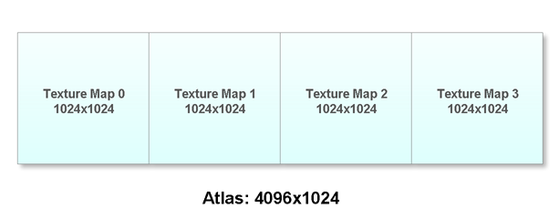
When implementing cascading shadow maps, you will be using more than one frustum slice: say, four or five. Valient's ShaderX 6 paper suggests a way to sample from four different shadow slices quickly in the shader by packing them into an atlas, perhaps like this:

This was the way we implemented it at first, but very soon after that I was desiring a little more versatility. If your graphics hardware will do non-power-of-two textures, then you may wish to have the number of shadow slices be an adjustable property; but if the texture maps are packed into a square like that, it's hard to know where to put a fifth one. So we changed the atlas layout to this:
This still works on power-of-two hardware (power-of-two textures don't have to be square!), and on more-versatile hardware, we can now easily add new textures onto the end.
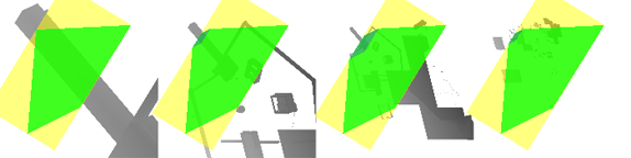
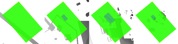
When your atlas is laid out in a line like this, and you add some runtime visualization to your game, it becomes very clear how much texture space is going unused. Here's a shot from The Witness's shadow maps:
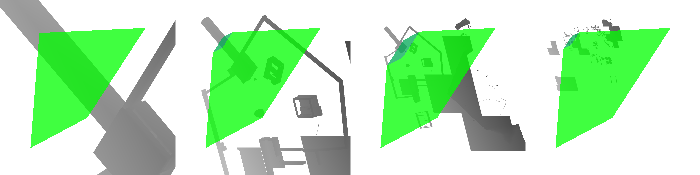
The frustum slices are shown in green. Obviously there is a lot of empty space between them. (For the purposes of visualization, we have left the pixels in the "empty space" filled with shadow map data, but anything that is not covered by green will never be visible in-game, so the game will run faster if we cull all that stuff!)
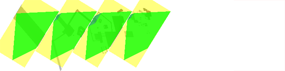
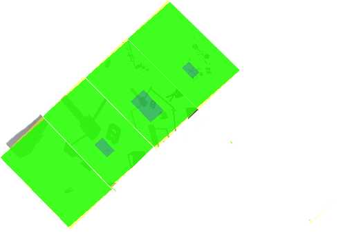
Because there's so much empty space, we could move our shadow maps closer together, and use less memory. But we need to be careful about it, because the whole point of the algorithm is that we need enough shadow map space to handle the worst case. Indeed, if you turn the camera a bit, you get this:
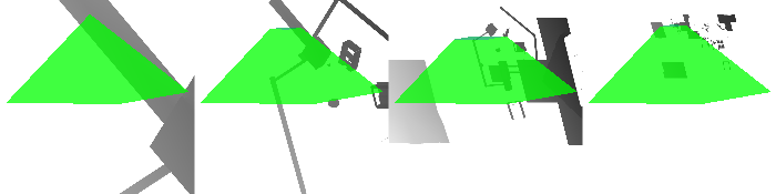
Now there is very little space between the maps, so you can't squeeze them together. Instead, all the space is toward the bottom of the atlas, and it is unclear how to use it effectively.
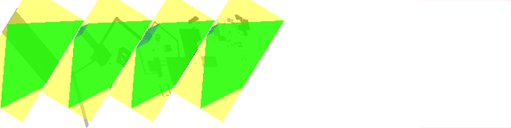
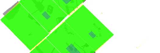
But there's a trick we can apply. Even though these shadow maps are all packed into one atlas, they are still indexed as separate units in the shader, which means we can transform them as separate units. So why don't we just rotate each individual shadow map by 90 degrees? Here's what happens to the image above when you do that:
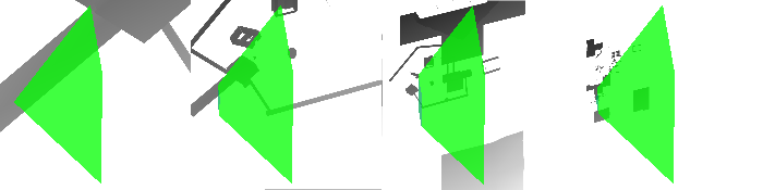
Now there is plenty of horizontal space and we can pack the maps all together! (Of course we don't need to render our shadow maps at the default orientation and then copy-and-rotate them in a post-pass; we can just rotate the up-vector of the camera used to render the shadow maps, so that we get the rotation for free.)
When we rotate the shadow maps like this, in order to render properly, our shader needs to realize that they are rotated; but Valient's system already provided a way to transform the shadow map coordinates based on map index, so rotating the maps fits directly into that scheme. Furthermore, if we are using any filter offsets to index into our shadow map, we need to ensure that those offsets get rotated (by either rotating the constants before uploading them to the shader, or by adding them before doing the map-to-atlas transform, depending on how your system is implemented).
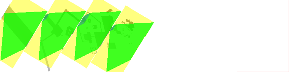
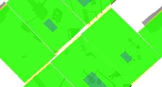
So how do we figure out how to pack the frustum slices together? Our implementation slides them to the left as far as we can make them go. First, we compute bounding rectangles for the frustum slices (bounding rectangles shown in yellow):
These rectangles are all oriented in the same direction, so we can just slide them to the left until they nearly touch:
We figure out the rectangle orientation by performing a brute-force uv-bounding computation on one of the frustum slices, then using that same orientation for all slices. By "brute-force uv-bounding computation" I mean that we just try a whole bunch of different angles and see which one fits the tightest. In the current implementation we try 100 different orientations spread over 90 degrees, so we find the best angle to within less than 1 degree of accuracy. (You only need to try 90 degrees, because at that point every angle has been covered by at least one of the sides of your rectangle).
The initial instinct was to use Shadow Map 0 to compute the rectangle orientation, but this didn't quite work out; because of the extreme pointiness of the first frustum slice, we sometimes end up with bounding rectangles that do not suit the other maps. Using any of the other shadow maps solves this problem (because their near plane tends to create a coherent bounding edge).
We're not done moving the shadow maps around. Besides just shifting the later shadow maps leftward, as above, we save some more space by shifting the first shadow map leftward based on the leftmost vertex in its frustum slice. (We don't do it based on the yellow rectangle, because that rectangle will almost always be poking outside of the atlas already. We don't need to make sure the whole yellow rectangle is inside the atlas; just the green frustum slice! Remember that the rectangles are just a tool to help us know how to pack.) So then we get this:
And we can shave off even more space by shifting the rightmost map upward or downward, whichever direction will allow it to slide further to the left (in this case, it's downward:)
Clearly we've saved a lot of space -- about half for this viewing angle. But we have to allocate enough texture space for the worst case, and the question is, what is that worst case? Empirically, for our game's FOV, we find that in this worst-case viewing angle we can chop off 25% of the texture map.
If you're on non-power-of-two texture hardware, you can just cut your map down and you are happy. If you are power-of-two-only, you can't do that, but you could use five frustum slices in the space that previously held only four.
Dealing with Overlapping
You can pack these rectangular areas together however you want, as long as they don't overlap -- at scene rendering time, your shader doesn't know or care how close these regions are to each other. Actually building the shadow maps in the first place has become a bit trickier, though. When each shadow map was in its own self-contained square region, we would just set up a viewport for that square, erase the contents, and render into it. But now, suppose we are rendering the shadow maps from left to right: while we are rendering the second shadow map, its viewport is going to inevitably overlap the first shadow map. We have to be careful not to write into the valid region of that first shadow map, or else we'll mess up the scene.
In our current implementation, we use DirectX9's API-provided clipping planes for this purpose. (The long sides of the yellow rectangles tell us exactly where to put our clipping planes. ) Clipping planes are deprecated in future versions of the API, so we would either switch to stencil testing or else do the clipping ourselves in the shaders.
Here's what the neighborhood of the worst case looks like:
It happens when you are looking sort-of in the direction of the light vector, but you are turned enough to the side that the view frustum has rotated to be diagonal relative to the axes of the texture map space. (If you are pointing directly along the light vector, your view frustum extrema are likely to be parallel to the axes of the texture map space.)
Deeper Thinking We Have Not Yet Done
We've saved this texture memory by doing what are essentially image-space operations. But it seems to me that one could somehow project these operations back to the 3D space that we use to compute the bounding spheres in the first place, and generate smaller spheres. The operation of rotating our texture maps means that we are folding our output space over on itself, using only half the possible orientations. The whole point of the bounding sphere is to permit the use of any orientation at all -- which we clearly, in retrospect, do not need. So it's probably possible to reformulate this algorithm in terms of a bounding hemisphere of some kind (or some shape that is somewhat near a hemisphere but allows frustum corner protrusions to poke out of it).
Saving Tremendously More Memory, if you are willing to copy your maps or else render them in multiple pieces...
The reason our system works is that once the shadow maps are packed into an atlas, the shader doesn't know or care where the boundaries of the shadow maps are. We can address the atlas at will, because in reality it is just one continuous texture map. This means that we can go even further, and place some of our shadow maps in the atlas in such a way that they cross the boundaries of the atlas and wrap to the other side. It looks discontinuous, but the shader being run at scene-render time does not care, if the texture is addressed in a wrapping mode. Here is a messy mock-up (not the output from an actual running version, because we haven't implemented this):
Unwrapped, easy-to-see version of texture space:
Wrapped vertically:
Wrapped horizontally:
In my done-by-hand mockup, the result is 46% the size required by the default packing in Valient's original algorithm. That's a lot of memory savings.
The catch is that, while it's easy to employ this mapping without additional expense, it's more expensive to generate. You have to either render a non-wrapped version of each shadow map and then copy it into its multiple destination pieces, or else you have to render each map in multiple passes. (It's always possible to arrange your maps so that one of them is unsplit, so for 4 frustum slices, you probably need 3 additional passes. Each pass has fewer objects, though, so maybe it's not too bad.)
If you are using pre-filtered shadow maps, then the filtering step is just a kind of copy anyway, so you would be able to do this packing essentially for free. We aren't doing any pre-filtering on The Witness, but if we do, it is likely we will switch over to this packing scheme. The memory savings are so huge, how could we not?
But I'd like to reiterate for clarity that at this time we have not implemented this wrapping-shadow-map scheme, so if there are any hidden gotchas, I don't know. We have only implemented the above 25% savings scheme (sliding the maps around, no wrapping).
Very Interesting. I don’t know much about rendering in 3D, because I’m just now wrapping up my first 2D project. One thing that I find very intriguing is number of ways that you can save memory, which is no doubt something I’ll need to read up on before my project is done. Thanks for the post.
did you consider using so-called deferred shadows?
Well, there are lots of ways to factor one’s rendering. The thing is that if I understand what is generally meant by “deferred shadows” it doesn’t really save any work. Then you have the extra complexities of dealing with translucent objects. In order to justify that, there has to be a really good benefit?
I guess you could soften the shadows in screen-space, which might look somewhat nice… but that cannot really be done without introducing motion artifacts.
In the first set of pictures where you show the yellow bounding box around the frustum, why do you not continue rotating the frustum and shadow map so they are facing towards the right allowing you to slide them together even closer?
thanks!
Deferred shadows allow you to save 75% of shadow map memory without these tricks. Of course there are a lot of caveats (performance will be worse in case there’s no overdraw in the forward rendered case, you’ll have to get the depth buffer somehow, etc.).
Also, I doubt viewports are going anywhere in future APIs. At least DX10/11 have the same support as in DX9.
Deferred shadows save a ton of memory though, which seems to be the main focus of your effort, so if you’re getting excited about 25% savings, you must really like 75% savings!
You only need to store a single slice of the frustum at a time since you go from:
* Render N slices
* Light the scene using N slices
To:
* For 1..N
* Render first slice
* Compute shadowing for anything in the first slice using the slice
Transparencies remain a problem.
Bah can’t edit, that’s supposed to be a loop, where you render each slice separateley, then use that slice, and then you don’t need it anymore so you can reuse the memory for the next slice.
Actually this post inspired me to write up my own little variation of cascaded shadow maps. You can find it here if you’re interested: http://sebastiansylvan.spaces.live.com/blog/cns!4469F26E93033B8C!210.entry
The main problem of deferred shadows is that as far as I know there’s no way to smooth the transitions cascades, or is there a way to achieve that?
BTW, you have a good point in your article. One problem that I can think of with your proposed approach is that you can probably notice the resolution change as you rotate the camera, but maybe that’s not such a big deal.
Dave: The basic point of doing shadows this way in the first place is image stability. To maintain stability, you can’t rotate or scale the frustum, and you have to translate it only by integer-texel amounts.
Arseny: Yeah, I clearly didn’t think enough about deferred shadows before posting. So it would make sense in terms of memory reduction. I do think that the shadow transitions could be smoothed in exactly the same way that we do it now (based on a 3D noise texture indexed by worldspace position). However, the lack of handling translucent objects is a serious drag.
Sebastian: One of the early implementations of shadows in The Witness worked like you describe (using the entirety of the visible parts of higher-res textures before moving on to lower-res textures). Rather than testing against the frustum slices, I would just compute the uv extents for the first texture map and proceed outward if they were not in [0, 1], recursively.
But there are drawbacks. The increased amount of change with camera motion, I find to be objectionable, and to my mind works counter to the basic idea of Valient’s algorithm. Maybe the noticeability can be mitigated, though, with enough smoothing between transition bands. (Even in the core Valient algorithm, because the choice is based on Z distance, there is some variation as the camera rotates, but it is relatively subtle (and we will probably look into eliminating even that, by testing Euclidean distance instead of Z, and my conjecture is that this will also make the worst case for our memory savings a lot better). Having weird corners poke further into the distance and then recede just really bugs me.
So whereas using the back side of the texture map indisputably provides higher image fidelity in a per-pixel PSNR kind of way, I find that the experience for a moving camera in a game world becomes worse, for the kind of game I am trying to do (where there is a lot of slow motion and subtlety). There may be games for which it is appropriate, but I haven’t found it to be so for this one.
I’m not at all trying to say that what we are doing right now is the Right Way to do it, either; just that there are reasons behind the decisions we have made so far.
Well, it doesn’t really *increase* the amount of change with camera motion, it just changes the *shape* of the border region, but it does so in a way which pushes the border region substantially away from the camera (even at its closest point, if you apply my little tweak) so it becomes *less* visible. The shape varies w.r.t. the camera orientation, but then so does your entire level so it’s not clear why locking the border region to the level (or rather, the light direction) rather than the camera would be worse. Either way you get something “sliding over” something else, doesn’t really matter if it follows the camera or the level to me…
The main point is losing the splitting plane, though, because it just completely screws up the position of the bounding sphere. Instead of euclidean distance I’d go with just using the bounding sphere instead, that will keep the border region rounded which may be a more pleasing shape. You’d still get the benefit of being able to push the bounding sphere out as far as possible, rather than being forced to waste a bunch of texels behind the camera. Once you get to that point, the extra resolution for the first splitting plane means (at least does for us) that the transition to the next splitting plane is subtle enough that you don’t need to worry about its shape.
Just a futher note: We don’t even do *any* blending between splitting levels, we just tweak the bounding sphere radii so that you can’t perceive the border, and having good texture utilization really helps with that.
I really hope other API designers are watching this blog, there’s some great ideas on display. Its interesting to me that a lot of the techniques and tricks of UV wrapping that you’re talking about, are actually things that texture artists have been doing for over a decade, to squeeze as much as possible into a power of two texture.
Sebastian: How exactly do you set things up so that there is no perceptual difference between levels? For the type of game we are doing (long view distance) there is always a substantial visual difference. (We are doing 4 frustum slices, 1400×1400 shadow map per slice currently). Differences are most prominent on vertical surfaces (doors and walls) since they tend to pop between layers simultaneously.
I’m completely ignorant about this stuff which is why I read this blog … but shouldn’t you also shift the leftmost rectangle up or down (in the opposite direction as the rightmost)? So as to chop that rectangle to its minimum necessary shape? By only shifting left it seems like you’re only doing half the job for that slice.
I grok that you can’t do anything interesting with the middle slices.
Umm, yeah. For some reason I didn’t think of that.
These slides don’t help a huge amount, because it only matters what they do in the worst case and they aren’t huge in the worst case. But they help a little.
(But it’s likely that if I go back to this, I will try the very-closely-packed wrapping version discussed at the end of the article.)
An update: It turns out that the “worst case” I had been talking about in the article, which forced us to turn the savings down below 25% until it was dealt with, was just due to an error in the bounding rectangle computation I was making. (I had been choosing the rectangle with the smallest area, which is really not what you want, and caused instabilities; I have changed it to the rectangle with the shortest side, and the algorithm behaves much better).
I implemented this, and also Zac’s point about tucking in the first rectangle, and everything is running at 25% savings with no viewport-related problems. We could probably go a little past 25% at this point, but I am leaving it there just to be safe and see how things go.
Update 2: I have thought further about the wrapped-texture-packing system that I outlined at the end of this posting, and it seems to be not as simple as I thought. That is to say, the worst case for that system seems not to be the same as the worst case for the current system, so I can’t use the current worst case to estimate memory savings, as I did above. This is something I will look further at in the near future.
Potentially related paper:
Packing Square Tiles into One Texture
http://www.antisphere.com/Research/Tiles.php
Very belated, but is saving 25% of your shadowmap texture memory really worth the week or three of effort? 4 x 1K x 1K is 8MB, so you’re talking about saving 2MB of texture, out of, say, 256 MB on a lower-end graphics card?
Er, for some reason I wrote that as if Z was 16 bit. I guess it’s 32 bit, so you’d be saving 4MB. Point still stands.
Right now our shadow maps are 1400×1400, so at 32-bit it would be closer to 8MB.
Still, no, I am not sure that it matters, unless shadow resolutions are even higher. Really I see this as two things… (a) a stepping stone toward a potential solution that could cut the memory in half, (b) a way of bringing this form of stable shadow maps closer into line with other CSM-related techniques (which tend to use less RAM if they are less concerned with quality).
But this isn’t the kind of thing that I would rush out and recommend everyone do, especially for a PC game. Maybe if they are shipping a 360 game.
“(which tend to use less RAM if they are less concerned with quality).”
Ah, ok, yeah, that’s a good point. I never ever considered anything other than the stable ones in my head, since I’m a firm believer in the “no artifacts when you rotate the camera without moving” school of rendering design, but yeah, it makes sense that if this is a major drawback of stable CSM that it’s worth improving it to help improve its viability compared to non-stable.
Hi guys, just been involved in a discussion on this topic offline and your posts were pointed out to me.
Transparencies are not too much of a problem with deferred shadowing as you can always render transparent surfaces on their own as part of another pass and add their shadow contributions as another channel in the deferred shadow buffer.
With Fable 3 we had an RGBA buffer that stored shadow amounts for opaque from the sun, transparency from the sun, opaque from spot lights, transparency from spot lights (shadow casting spotlights were not allowed to overlap in world-space, as a result).
In the case of a window, it was possible to get shadows on the window itself and the geometry behind it. In the general case we found that was all that you needed, and two overlapping layers of transparency was rare enough to not justify depth peeling any further. YMMV.
Cheers,
– Don